
How to Turn Non-Metallic Requirements Around RF Connectors and Antennas into Manufacturable Parts
Around high-frequency connectors, RF-sensitive areas, radomes, and feed lines, designers may call for non-metallic construction, electrical insulation, low dielectric loss, low moisture uptake, non-magnetic behavior, or custom geometry. The next challenge is turning those requirements into small engineering plastic parts that can actually be made and delivered.
After outdoor fastening points in Part 1 and PCB/power-module standard parts in Part 2, this article looks at another area that often slows down mechanical design and sourcing: small non-metallic parts around RF connectors and antennas. These parts are not always raised because they are guaranteed to affect RF performance. More often, the design team has already set a specific condition: no metal in this location, insulation is required, a sleeve sits close to the feed line, a washer must maintain radome spacing, or a support should not create an unnecessary conductive path.
1. Separate the RF Core from the Peripheral Small Parts
High-frequency connectors, optical connectors, antenna structures, and RF modules all involve specialized core design. Fiber-optic ferrules, antenna elements, and active RF components are outside the scope of general engineering-plastic part development.
This article focuses on the smaller parts around those core areas: insulating sleeves, non-metallic screws and nuts, washers, bushings, standoffs, supports, locating features, connector-adjacent housing parts, radome supports, and custom isolation components.
These parts may not define the RF design itself, but they may still be required to be non-metallic, electrically insulating, low in moisture uptake, dimensionally stable, weather-resistant, or geometrically specific. Once “no metal” becomes a real part requirement, material and process have to be evaluated together.
At that point, mechanical design and procurement start asking practical questions: Is there a standard size that fits? Can this material and geometry be produced consistently? Which supplier can support it? Can lead time and quality requirements match the development schedule?
2. Where Do Non-Metallic Requirements Most Often Outgrow Standard Parts?
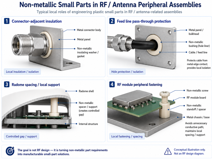
| Application Area | Common Requirement | Part Types to Consider |
|---|---|---|
| Around high-frequency / optical connectors | Electrical insulation, precision dimensions, stable dielectric properties, and avoidance of metal contact; the ferrule itself is not treated as a general fastener. | Connector-adjacent insulators, sleeves, locating parts, small housing components, mounting washers, and custom supports. |
| RF components / signal-sensitive areas | Non-metallic, non-magnetic, insulating, low-loss candidate materials, and avoidance of unnecessary conductive paths. | Non-metallic screws and nuts, standoffs, thin washers, and hole-isolation parts. |
| Radomes / outdoor antenna areas | Low moisture uptake, weatherability, dimensional stability, and controlled spacing between the radome and internal structure. | Radome spacers, antenna supports, locating posts, PVDF/PPS/PEEK washers, and custom isolators. |
| Feed-line / connector areas | Insulation, positioning, and avoidance of direct metal contact; material and geometry must be checked when the part is close to the signal path. | Feed-line sleeves, bushings, washers, custom standoffs, and connector supports. |
Microwave and high-frequency fixtures or test hardware may raise similar needs for non-metallic, low-interference, dimensionally stable, or low-volume custom parts. Those applications should be evaluated separately based on fixture function, frequency, load, and manufacturing method.
3. Selecting a Material Is Only One Part of Defining the Component
High-performance engineering plastic data is not hard to find. Once part development begins, the questions become much more specific: Is the wall thick enough? Can the threads be produced consistently? Can the sleeve ID and OD tolerances be held? Will the part stay within budget?
That is why it helps to involve the supplier early for small parts around RF and antenna hardware. The design team sees location and function. Procurement sees cost, volume, and lead time. Manufacturing has to confirm that material, geometry, and process can all work together.
| Material Direction | Best-Fit Requirements | What to Confirm Before Production |
|---|---|---|
| PTFE / PFA | Low dielectric loss, electrical insulation, and candidate materials for locations close to an RF path. | Creep, support capability, fastening, and long-term load. PTFE is typically machined, while PFA can be injection molded; choose the process based on geometry and volume. |
| PEEK | Locations that require non-metallic construction, electrical insulation, heat resistance, strength, and dimensional stability together. | Dielectric behavior for the actual application, cost, material availability, and processing method. |
| PEI | Connector-adjacent parts with clearer requirements for insulation, flammability, and dimensional stability. | Weatherability, chemical exposure, and long-term load in the actual environment. |
| PPS / PPS+GF | Supports or isolators that need low moisture uptake, dimensional stability, heat resistance, and production consistency. | Do not treat PPS as a default low-loss material for every RF-sensitive area. Confirm grade properties, glass-fiber reinforcement, dielectric behavior, and part design. |
| PVDF | Isolation or protective parts around outdoor radomes and housings in wet or corrosive environments. | Do not position PVDF as a general low-loss material for RF-sensitive areas. Confirm long-term load and temperature. |
4. Standard Parts, CNC Machining, or Injection Molding—Start with the Current Stage of the Requirement
The right manufacturing approach depends on where the requirement is in the development process. If a standard screw, nut, washer, or standoff already fits, that is usually the fastest path. If only the diameter, hole size, thickness, or length differs, CNC machining, cutting, or simple customization may be better for prototypes and validation. When the geometry is stable and volume is predictable, tooling and injection molding are better suited to long-term supply.
The most useful discussion brings the installation location, drawing dimensions, material limits, volume, and sample timing together so that material and process can be evaluated at the same time.
| Current Part Requirement | Manufacturing Route to Evaluate First | Why It Fits |
|---|---|---|
| An existing standard part matches | Start with an available standard part. | Fastest path to sample evaluation. |
| Diameter, hole size, thickness, or length differs slightly | CNC machining, cutting, or simple customization. | Well suited to prototypes and low-volume validation. |
| Special geometry or integrated functions | Build a custom part from the drawing. | Can combine support, positioning, and isolation in one component. |
| Specification and volume are stable | Tooling and injection molding. | Better suited to long-term supply and cost optimization. |
5. Turn a Non-Metallic Requirement into a Deliverable Part Solution
Developing a small part around an RF connector or antenna starts with a defined set of conditions: where the part sits, what it must isolate, what load it carries, what structures are nearby, what dimensions are required, expected volume, and whether the customer has material, flammability, or dielectric requirements.
Once those conditions are clear, the discussion can move from a rough requirement to a part that can be quoted, sampled, and manufactured. It may be a PEEK screw, a PTFE or PFA sleeve, a PEI insulator, a PPS spacer, or a PVDF isolation washer used around an outdoor radome.
The final deliverable is a part whose dimensions, material, process, volume, and quality requirements all work together. Link Upon can help organize those requirements into a manufacturable engineering-plastic part solution that can be evaluated, produced, and supplied. Any RF impact should still be confirmed by the RF or antenna engineering team through simulation and testing.
This article is part of the “Pain Points in Electronic and Communication Equipment Components” series.
- Part 1: Which Outdoor Telecom Fastening Points Are Good Candidates for Weather-Resistant Non-Metallic Parts?
- Part 2: When Should Small Parts in PCB and Power Modules Be Re-Evaluated?
- Part 3: How to Turn Non-Metallic Requirements Around RF Connectors and Antennas into Manufacturable Parts
Note
This article provides general material and application guidance. Final material selection should be based on grade-specific data, dielectric properties, frequency and operating environment, geometry, load, temperature, assembly method, documentation requirements, and customer specifications. RF impact should be determined by the relevant engineering team through simulation and test results.
